The Kaiser Geary Medical Office Building (MOB) is a high-rise medical office building located in San Francisco, California, and was constructed in 2000. The $60 million building is eight stories with an atrium and five additional floors of underground parking. Each floor has an area of 32,800 sq.ft. and the building has a total floor area of 261,600-sq.ft. The facility contains a cafeteria, a large data/telecom room, doctor's offices, nurse's stations, a full pharmacy, exam rooms, waiting areas, a cancer center, neurology, orthopedics, otolaryngology, urology, dermatology, podiatry, ultrasound, radiography and other imaging services. This outpatient facility also houses procedure rooms for performing minor and non-invasive medical procedures. The project program was for 150 provider offices and all the necessary support spaces.
The project site is located in a mild weather climate with summer conditions (0.1 %) of 84°F DB and 66°F WB and winter conditions (0.2%) of 41°F DB. The climate has 3,080 heating degree days. Architecturally, the building has a rectangular floor plate with the long sides facing north and south for solar control. The floor plate is divided into two halves, east and west, by a 3-story atrium. The envelope is comprised of cement plaster, metal frame walls with R-19 rigid insulation and concrete deck roof with built-up rigid insulation. A layer of R-19 rigid insulation board provides them1al isolation between the first floor and the parking garage level. The glazing is a clear single-pane float glass with 88% visible light transmittance. Doctors and nurses offices are located along the building perimeter and architectural interior light shelves provide indirect natural light for the perimeter spaces. A solar shade-cloth provides solar protection and prevents glare on interior work surfaces. The facility has an overall window-to-wall ratio of 45%, but is 27% below California's Energy Code.

A 15,000 gallon water storage tank is provided along with diesel and electric fire pumps, combination stand pipes and full sprinkler systems. High rise stair pressurization, vestibule ventilation, and atrium exhaust systems on emergency power are included. Double containment fuel oil storage with duplex pumps in the garage feed the roof mounted emergency generator and day tank. Domestic water booster pumps, gas-fired domestic water heaters, medical and control air compressors, and medical vacuum pumps round out this highly serviced building.
Thermally powered VAV diffusers have historically been used in retrofit applications to provide additional zoning for existing systems. The Kaiser Geary Medical Office Building is the first significant new building in the USA to use thermally powered VAV diffusers as the basis of design. An improved DDC approach for reheat control was developed, and a prototype tested at the factory before construction commenced. This project demonstrates why medical office buildings particularly can benefit from this HVAC system type. Other building types where fully enclosed offices are needed, such as attorney offices, may also be suitable for this system given the improved zoning the system affords.
Medical office buildings contain many individual doctor's offices, exam rooms and special procedure rooms, with dressed and undressed patients. As medical office buildings usually are provided with reheat on interior as well as exterior zones, there is a significant cost associated with heating hot water distribution, VAV box hook-ups and controls. Conventional VAV boxes with reheat are typically zoned at no less than three to five or more rooms per thermostat. If each room could have its own temperature controls, the comfort of patients and staff would be enhanced - but how can that be done given limited construction budgets?
During schematic design Kaiser expressed interest in considering VAV diffusers as they had used some in a small project which had hand held remote controls. A cost study was undertaken with the on-board contractor which showed that "wired" or remote controlled VAV diffusers were more than the budget, but that thermally powered VAV diffusers could be provided for the same cost as a conventional VAV reheat system. This is because the number of reheat coils is greatly reduced, and they are often able to be located close together around each shaft, which reduces the amount of heating hot water piping dramatically. Also the duct distribution is greatly simplified, reducing the amount of ductwork that needs to be installed.
Thermally powered diffusers have a built-in thermostat and VAV dampers. The thermostat/actuator is a small brass cylinder containing petroleum-based wax that responds to room temperature by expanding and contracting, which in turn modulates a damper actuator in the diffuser that regulates air volume. Usually, the damper movement results in a constant discharge velocity, which improves part load air distribution by maintaining throw and avoiding cold air dumping which can occur at low discharge velocities. Room return air is induced by the supply air and routed over the self-contained thermostat to sense room temperature for control. There are no external connections (other than sheet metal duct) required for operation. Thermally powered diffusers have been reliably in service for over twenty-five years.
There are DDC controlled diffusers available that require power and control wiring to operate, but the cost of such systems is usually prohibitive, and the objective was to provide accurate control of each room for the same cost as a conventional system with VAV boxes and reheat. However, in using affordable thermally powered diffusers, supply air temperature control must be resolved. Simultaneous heating and cooling from a single temperature source is not possible, so each group of diffusers must have the same type of load - either heating or cooling. In a large new building this is most practically accomplished by means of hot water reheat coils for each exposure and interior space. Individual air handling units per exposure and interior space would be better, but are usually difficult to integrate into the building economically. In the case of the subject project, Kaiser has a policy of providing separate air handling systems for interior and perimeter areas, which provided a good zoning basis for optimum supply air temperature control.
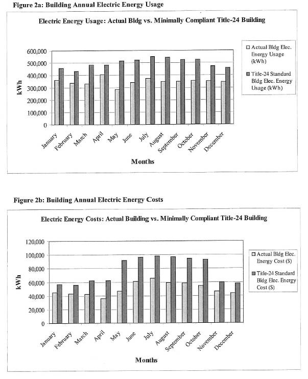
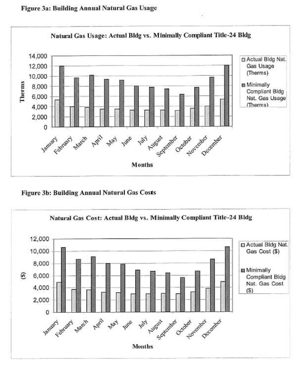
The building's actual electricity and gas usage for one year have been compiled from the facility's utility bills and plotted in Figures 2 and 3. A detailed DOE-2 energy model was prepared for the facility to generate the "Standard Building", which is a minimally code compliant building with equivalent square footage, process and plug loads and identical operating schedules. The annual electric energy & costs and natural gas usage & costs for the equivalent "Standard Building" was obtained and has been plotted in Figures 2 and 3. The energy costs of the "Standard Building" were calculated based on the modeled energy use and an identical utility rate schedule as the actual facility. The graphs provide a comparison between the actual building energy consumption from the utility bills and the energy consumption of a building that meets the minimal requirements of the California Title-24 energy codes.
The project design minimizes building energy consumption, being 27% below California's Energy Code, thereby reducing the environmental impact of electricity generation. The DOE-2 energy model showed that the building design resulted in a saving of 1,859,430-kWh/year over a standard building designed to comply with California's Title-24 Building Energy Standards. Approximately 1-1/3 pounds of CO2 are produced for each kilowatt of electricity generated. The 1,859,430-kWh reduction in energy use corresponds to the elimination of over 2,473,040lbs/year of the greenhouse gas C02.
The use of thermally powered VAV diffusers can and should be applied to new construction as well as retrofit HVAC systems which has been the main market for the product to date. For the same cost as a conventional VAV reheat system, this approach offers improved comfort through individual room temperature control, better air distribution at part load, simplified duct distribution, greatly reduced reheat piping, simple, robust controls, Iower energy use, and easy commissioning and maintenance.


